Sunday, September 21, 2014
Remote Field Strength Meter Circuit Diagram

Audio Milli Volt Meter Circuit Diagram
Simple Audio Milli Volt Meter Circuit Diagram

Sourced By : http://circuitsdiagram-lab.blogspot.com/2013/11/simple-audio-milli-volt-meter-circuit.html
Audio Milli Volt Meter Circuit Diagram
Simple Audio Milli Volt Meter Circuit Diagram
Friday, May 17, 2013
40 Segment LED S Meter
 40 Segment LED S-Meter Circuit
Provide your radio with a actual cord signal, again acclimatize the HIGH LEVEL pot to the beginning of anecdotic the aftermost LED (all LEDs on). Remove the arresting completely, again acclimatize the LOW LEVEL pot to the beginning of no LEDs illuminated.
If your radios S-meter achievement is greater than 5 volts, you mau ambition to alter the HIGH LEVEL pot with a 10K resistor, and accommodate pin 6 of the right-most 3914 with the cathode of a 6.1 volt zener diode, pulled up to 13 volts with a 1K resistor. The anode should be affiliated to ground. You may use a college voltage zener if necessary.
This agreement provides 10ma per LED segment. Change the ethics to the resistors and pots to change the drive accepted to the LEDs. R1=12.5/I R2=25/I R3=37.5/I R4=50/I area I = the adapted LED current
Monday, April 8, 2013
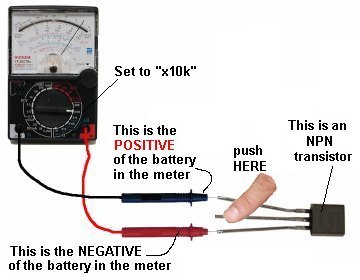
FINDING THE COLLECTOR and EMITTER Set the meter to x10k
Set the meter to "x10k."
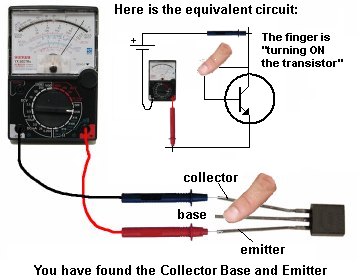
For an NPN transistor, place the leads on the transistor and when you press hard on the two leads shown in the diagram below, the needle will swing almost full scale.
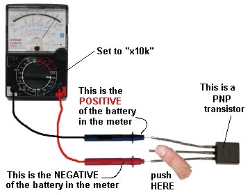
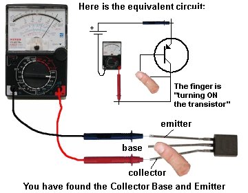
For a PNP transistor, set the meter to "x10k" place the leads on the transistor and when you press hard on the two leads shown in the diagram below, the needle will
swing almost full scale.
Track the damage capacitors elco with ESR meter
 Many technicians get around this problem by directly replacing all existing Elko, the Elko-regardless of whether Elko is corrupt or not. It is generally quite successful. But sometimes the quality is not good substitutes Elko, so the damaged aircraft back after use for some time. Replace all of Elko is also a problem for yourself if the circuit is improved a lot using Elko. The use of ESR-meter proved to be the most appropriate choice to solve the above problems. We suggest that ESR-meter is a must-have tool for every technician after avo-meter.
- Elko track damaged by the time more quickly because they do not need to remove the Elko (in-circuit tester) one by one.
- Elko only replaced damaged
- Can be used to check the quality of new and used Elko. It is certainly advantageous to utilize part of the former ex-change machine pcb. Sometimes the plane is damaged due to repeated just posted a new Elko was poor quality.
- Elko that if the check using the ohm-meter sometimes the results are deceptive. Because if you checked with ESR ESR-meter turns his already large.
- Can be used to check the flyback is short in the primary coil (between the B + with a pin-pin-collectors), def a short yoke, the power tranfo a short primer.
- To find out if re-chargeable batteries are still good. Re-chargeable battery that is damaged ESR was generally higher when compared to a still good.
- To keep track of printed lines leaking / short
- By comparing the capacitors are still good, ESR-meter can be used to check the value of thousands pf capacitor.
- ESR meter can not be to find Elko leak or short. Fortunately rare short Elko damage.
- ESR meter to check the fit only Elko with values ranging 0.47uF and above.
- The first is caused because of the connection quality is poor constituents. It can be found in Elko Elko New and old.
- Both are caused due to dry the liquid electrolyte due to evaporate or leak, which can be found at the old Elko. Are the consequences of large ESR Elko turned into?
- Elko is a working principle can be "in-fill and waste of" electric charge repeatedly. Thus ESR Elko-charging current will be passed this exile repeatedly in accordance with the working frequency of the circuit. And we certainly have understood that if bypassed resistor will generate heat flows in accordance with the magnitude of the current strength through resistance value and the corresponding magnitude. Similarly, the Elko with ESR, the greater the greater the ESR value of the heat arising in Elko, and the higher the frequency the greater the heat generated. This heat can eventually cause the electrolyte evaporates into a gas and seeped out, so the value of Elko will turn down. In the specific cases heat can even make Elko explode.
- On a circuit that works at high frequencies Elko should have zero resistance to the high frequency signal. If the ESR of the resistance turned into Elko is no longer zero, and if the resistance value change is large enough to make the workings of the chaotic circuit.
- Check out all the Elko with ESR-meter at the SMPS, Horizontal and Vertical and immediately replace it if the ESR problem.
- Check visually (with a magnifying glass if necessary) solder-solder on the SMPS, the output Horizontal, Vertical output, and the CRT socket pcb and soldering again if there appears a problem or suspicious solder it.
- Both of these were able to eliminate the difficulties that may arise and difficult to trace, so the use of ESR meter can shorten repair time.
- Once the tool is finished
- Collect some old Elko is still good. Find Elko pcb traces of the plane, made in Japan or Europe the original (former aircraft engine change) because of generally good quality for use as a reference.
- Grouped on the basis of a value less dar 2.2uF, 4.7uF is less than, less than and greater than 10uF 10uF.
- Try using the ESR-meter to measure each group, and mark the position of the needle meter on each group
- These markers can be used as a reference to the appointment of Elko ESR is still good.
- If the meter needle to deviate less from the reference mark, the mean ESR Elko is not good.
Friday, April 5, 2013
LED Power Meter


