Showing posts with label switching. Show all posts
Showing posts with label switching. Show all posts
Wednesday, June 5, 2013
Humbuckers Switching Guitar Wiringcircuit Schematic

Way Switch Wiring Diagram.

Figure 8 Is A Typical 4 Way Circuit Diagram Bear.

Way Switch Wiring Diagram.
100664d1320079616 4 Way Fender Switch Wiring Help Swl4connections1 Jpg.

Way Switch Wiring Diagram.

Of A Crl Or Oak Grigsby 5 Way Rotary Switch Switch Pickup Selector.

Humbuckers With 5 Way Switching Guitar Wiring Circuit Schematic.
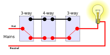
350px 4 Way Switches Position 4 Svg Png.

Three Way Switch Wiring Diagram.
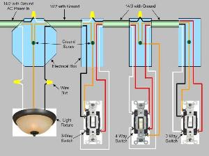
Way Switch Wiring Diagram Power Enters At Light Fixture Box.
Tuesday, April 30, 2013
Soft Start For Switching Power Supply
Switching power supply whose output voltage is appreciably lower than its input voltage has an interesting property: the current drawn by it is smaller than its output current. However, the input power (UI) is, of course, greater than the output power. There is another aspect that needs to be watched: when the input voltage at switch-on is too low, the regulator will tend to draw the full current. When the supply cannot cope with this, it fails or the fuse blows. It is, therefore, advisable to disable the regulator at switch-on (via the on/off input). until the relevant capacitor has been charged. When the regulator then starts to draw current, the charging current has already dropped to a level which does not overload the voltage source.
Circuit diagram:
Circuit diagram:
Soft Start Circuit For Switching Power Supply
The circuit in the diagram provides an output voltage of 5 V and is supplied by a 24 V source. The regulator need not be disabled until the capacitor is fully charged: when the potential across the capacitor has reached a level of half or more of the input voltage, all is well. This is why the zener diode in the diagram is rated at 15 V. Many regulators produced by National Semiconductor have an integral on/off switch, and this is used in the present circuit. The input is intended for TTL signals, and usually consists of a transistor whose base is accessible externally. This means that a higher switching voltage may be applied via a series resistor: the value of this in the present circuit is 22 kΩ. When the voltage across the capacitor reaches a level of about 17 V, transistor T1 comes on, whereupon the regulator is enabled.
Source: National Semiconductors
Subscribe to:
Posts (Atom)

