Showing posts with label schematic. Show all posts
Showing posts with label schematic. Show all posts
Wednesday, June 5, 2013
Humbuckers Switching Guitar Wiringcircuit Schematic

Way Switch Wiring Diagram.

Figure 8 Is A Typical 4 Way Circuit Diagram Bear.

Way Switch Wiring Diagram.
100664d1320079616 4 Way Fender Switch Wiring Help Swl4connections1 Jpg.

Way Switch Wiring Diagram.

Of A Crl Or Oak Grigsby 5 Way Rotary Switch Switch Pickup Selector.

Humbuckers With 5 Way Switching Guitar Wiring Circuit Schematic.
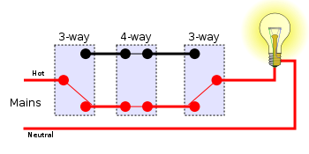
350px 4 Way Switches Position 4 Svg Png.

Three Way Switch Wiring Diagram.
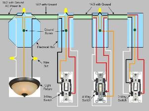
Way Switch Wiring Diagram Power Enters At Light Fixture Box.
Thursday, May 30, 2013
Typical Electric Starter Schematic Diagramcircuit Schematic

Fiat Spider Wiring Diagram And Electrical Schematics.

Wiring Diagram.

Acura Integra Electrical Wiring Diagram 98 01 Circuit Schematic.

Chevrolet Tahoe Blazer Electrical Wiring Diagram Circuit Schematic.

Wiring Diagram.

Lancer Evo Ix Wiring Diagram Electrical System Circuit Schematic.

This Wiring Diagram And Electrical Circuit Schematic Apply For 2002.

Diagram Electrical Circuit Diagram Related Posts Wiring And Connectors.

The Following Wiring Diagram And Electrical System Applies For Toyota.

250 Typical Electric Starter Schematic Diagram Circuit Schematic.
Friday, April 12, 2013
30W CLASS AB AMPLIFIER CIRCUIT WITH TIP3055 TIP2955 SCHEMATIC DIAGRAM
30W CLASS AB AMPLIFIER CIRCUIT WITH TIP3055/TIP2955 SCHEMATIC DIAGRAM
To set the above amplifier up, set R1 to max and R12 to 0. After doing this successfully, power on the amplifier. Set R1 so that the measured output offset is between 30 and 100mV. Once set, adjust R12 slowly to achieve a quiescent current of around 120mA. Keep checking the quiescent current as the amp heats up as it might change due to voltage drop changes in the output devices caused by heat. The heatsinks should be 0.6K/W or less for two amplifiers.
Read More..
To set the above amplifier up, set R1 to max and R12 to 0. After doing this successfully, power on the amplifier. Set R1 so that the measured output offset is between 30 and 100mV. Once set, adjust R12 slowly to achieve a quiescent current of around 120mA. Keep checking the quiescent current as the amp heats up as it might change due to voltage drop changes in the output devices caused by heat. The heatsinks should be 0.6K/W or less for two amplifiers.
Subscribe to:
Posts (Atom)

