Showing posts with label battery. Show all posts
Showing posts with label battery. Show all posts
Sunday, September 21, 2014
USBCELL Revolutionary NiMH Rechargeable Battery
A revolutionary NiMH rechargeable battery - the USBCELL, saves you money and battery waste and is easy to recharge from a USB port. When empty, all you have to do is to plug the USBCELL in PC port. This cool eco-friendly gadget is of AA sized battery and costs $10-20. USBCELL has also been designed in the AAA format with an instant foldout full-size USB, and with a mini-USB. AA cells can also be used with convertors to create C and D size cells.


Build a 12V 7 2Ah SMF Battery Charger Circuit Diagram
Build a 12V 7.2Ah SMF Battery Charger Circuit Diagram. The LM317 is an adjustable three-terminal positive-voltage regulator capable of supplying more than 1.5A over an output-voltage range of 1.25 V to 37 V. It is exceptionally easy to use and requires only two external resistors, R2’ and R2” (R2= R2’+ R2”) to set the output voltage. Furthermore, both line and load regulation is better than standard fixed regulators. In addition to having higher performance than fixed regulators, this device includes on-chip current limiting thermal overload protection, and safe-operating-area protection. All overload protection remains fully functional, even if the ADJUST terminal is disconnected. By connecting a fixed resistor, R1 the ADJUST and OUTPUT terminals, the LM317 can function as a precision current regulator. An optional output capacitor can be added to improve transient response.
Schematic Diagram using LM317

The ADJUST terminal can be bypassed to achieve very high ripple-rejection ratios, which are difficult to achieve with standard three-terminal regulators. A capacitor of small value should be connected across the input pin of LM317 and ground, particularly if the regulator is not in close proximity to the power-supply filter capacitor.
Please note that the output can go no lower than 1.25 Volts.The Input voltage must be about 3 Volts above the desired Output Voltage. So input voltage should be around 18V.So a transformer with the secondary voltage of 17 V is used.
Determining the Values
Vo is calculated by following formula , Vo = Vref * ( 1 + R2/R1 )
Where Vo is the voltage drop across the output i.e voltage applied to the charge the battery.
Here Vref = 1.25.Making R1 a standard value, like 220 Ohms sets the current through R2 as well. Now all we have to do is select the value of R2 to give us a voltage drop of our desired V OUT, minus the 1.25 Volts across R1.
So for Vomaximum=15 v and Vominimum=12 v we get respective values of R2minimum=1K8 and R2maximum=2K3 which we will get by keeping R2’=1k8 and R2”=500 Ohms (variable).
The most commonly used OPAMPS are 741 and 324. IC741 is used in close loop configuration and LM324 in open loop configuration. i.e. LM324 mainly used as comparator while 741 for amplification,addition etc
LM317 regulates the Output at 1.25 Volts above the Reference pin. Knowing this the value of this resistor sets the current through both resistors. The current drawn by the Reference pin is small and can be ignored as long as the current through the resistors is around 1 mA to 10 mA.
Testing your Circuit
Output voltage can be varied and obtained as wanted(between 12v and 15v,minimum and maximum charging voltages. Observed voltage values at INPUT ,OUTPUT and ADJUST pins is shown in table.While testing take enough precaution as not to short OUTPUT and ADJUST pins as it may damage the transistor BC 547,whose collector is connected to adjustment pin.
| ADJUST | OUTPUT | INPUT | Vref |
| 13.7 V | 12.47 V | 15.01 V | 1.23 |
The difference between voltage at output pin and adjustment pin is 1.23 (~1.25) which is the reference voltage Vref. Current rating of battery to be charged 7.2 Ah 12v, short circuit current Isc = 720mA .Using multi-meter check the short circuit current.If the Isc shows a different value than expected,it can be changed by increasing or decreasing the load connected between the emitter of the transistor T1 and ground.
Working of Charger Circuit
The circuit uses two LEDs as indicators; one for signaling charging ON condition,and the other as an indicator , when charging voltage falls below its terminal voltage (~12 volts). Terminal voltage can be adjusted by adjusting the 1k Trimpot. The output voltage range can be adjusted by 500 ohm Trimpot. LM324 is used in comparator circuit,after the rectifier circuit. Comparator will compare the voltage levels,and if the output voltage is less than the charging voltage,the voltage across the red LED will go high thus indicating drop in charging voltage.

Diode Protection for LM317T
If the battery is connected to the charger but unplugged from the power source, you end up with the input voltage of the circuit disconnected while the output voltage is still present. Some regulators can be damaged by this, and thus diodes are put into the circuit to protect them.
Applications
SMF batteries or VRLA batteries (valve-regulated lead-acid battery) are made in an eco-friendly, ISO Certified & modern plant with a large manufacturing capacity and are being sold worldwide. There is a wide range available to suit all applications of standby power requirement’s, for example:
- UPS (Uninterrupted power supply)
- Inverter and Emergency Lights
- Telecommunication equipment
- Fire Alarm & Security Systems
- Railway Signaling
- Electronic Attendance & Cash Registers
- Solar Lanterns and Systems,
etc. come in factory charged conditions and have a high shelf life thereby requiring longer time intervals between recharging of batteries in stock. Source : Link
Wednesday, May 29, 2013
Battery Charger Indicator Circuit
This is battery charger indicator circuit diagram.When the battery charges it shows by the LED this circuit can be used with 12V battery with charging current less than 1A.

Note
# Dont use this circuit for the batteries Which has more than 1A charging current
# Fix this circuit on a PCB
Read More..
Note
# Dont use this circuit for the batteries Which has more than 1A charging current
# Fix this circuit on a PCB
Wednesday, April 10, 2013
Automatic Battery Backup Circuit
This is a design schematic for battery backup circuit. The diode-OR connection is the simplest link between backup battery and a main supply with a load. But, when the battery voltage is greater than main supply voltage, it will not work. To solve this problem we can use the circuit below. This is the figure of the circuit;

This circuit has the backup supply of 9V battery and main switch-mode supply voltage ranges from 7V to 30V. It uses the MAX931 which is an ultra-low-power comparator with a 1.182V band gap reference. When it is used in normal condition, the battery’s negative terminal floats, the three parallel-connected n-channel FETs are off, and the comparator output is low. The n-FETs will turning on, the negative terminal of the battery will be grounded and the comparator’s output goes high when the main voltage declines to 7.4V.
To eliminate the supply-rail glitch that would otherwise happen when switching from the battery to the main supply, the delay was used. It can be done by using the R6, C1, and D1. An unacceptable reset in the system’s microcontroller can be occurred while the glitches. For proper operation, the value of R3 and R4 should set the hysteresis in the MAX931 to 800mV. [Circuit Source: maxim-ic.com]
Sunday, April 7, 2013
2 Volt Battery Monitor by IC LM3914
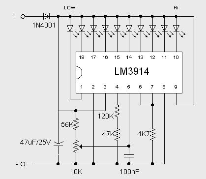
This 2 Volt Battery Monitor by IC LM3914 circuit makes it possible to monitor the charging process to a higher level. Adjustsments end are simple and all you need is a digital voltmeter for the necessary precision. Connect an input voltage of 12.65 volt between the positive and negative poles and adjust the 10K potentiometer until the LED 10 lights up. Reduce tension and the sequence of all other LED lights. Control has been an enlightening about 11.89 volts.
At 12.65 volt and higher the battery is fully charged, and 11.89 is considered "empty". This circuit, with the components shown, uses less than 10 mA. Of course you can adapt this circuit for their own needs, making small modifications. The previous circuit is set to "point" mode, which means only one LED at a time goes on. To use the mode of "bar", then connect pin 9 to the positive supply rail, but obviously with increased current consumption. The brightness of the LEDs can be adjusted up or down by choosing a different value for the 4K7 resistor connected to pin 6 / 7.
At 12.65 volt and higher the battery is fully charged, and 11.89 is considered "empty". This circuit, with the components shown, uses less than 10 mA. Of course you can adapt this circuit for their own needs, making small modifications. The previous circuit is set to "point" mode, which means only one LED at a time goes on. To use the mode of "bar", then connect pin 9 to the positive supply rail, but obviously with increased current consumption. The brightness of the LEDs can be adjusted up or down by choosing a different value for the 4K7 resistor connected to pin 6 / 7.
Subscribe to:
Posts (Atom)

