Showing posts with label volt. Show all posts
Showing posts with label volt. Show all posts
Sunday, September 21, 2014
TL496 3 to 9 volt converter Circuit Diagram
This is simple Simple TL496 3 to 9 volt converter Circuit Diagram. it uses the TL496 power supply controller, a coil and a electrolytic capacitor. The maximum output voltage is actually 8.6V and current is around 80mA.The input current (the current drawn from the batteries) is 405mA at the maximum output current. Without load the current consumption is 125µA and the batteries life is around 166 days.
TL496 3 to 9 volt converter Circuit Diagram


Audio Milli Volt Meter Circuit Diagram
Build a simple audio Milli volt meter circuit diagram. This Audio Milli Volt Meter Circuit has a flat response from 8Hz to 50 kHz at -3 db on tbe 10-mV range. The upper limit remains the same on tbe less sensitive ranges, but the lower frequency limit covers under 1 Hz.
Simple Audio Milli Volt Meter Circuit Diagram

Sourced By : http://circuitsdiagram-lab.blogspot.com/2013/11/simple-audio-milli-volt-meter-circuit.html
Audio Milli Volt Meter Circuit Diagram
This is a simple audio Milli volt meter circuit diagram. This Audio Milli Volt Meter Circuit has a flat response from 8Hz to 50 kHz at -3 db on tbe 10-mV range. The upper limit remains the same on tbe less sensitive ranges, but the lower frequency limit covers under 1 Hz.
Simple Audio Milli Volt Meter Circuit Diagram
Sunday, April 7, 2013
2 Volt Battery Monitor by IC LM3914
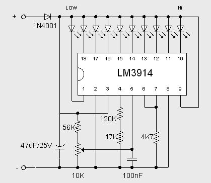
This 2 Volt Battery Monitor by IC LM3914 circuit makes it possible to monitor the charging process to a higher level. Adjustsments end are simple and all you need is a digital voltmeter for the necessary precision. Connect an input voltage of 12.65 volt between the positive and negative poles and adjust the 10K potentiometer until the LED 10 lights up. Reduce tension and the sequence of all other LED lights. Control has been an enlightening about 11.89 volts.
At 12.65 volt and higher the battery is fully charged, and 11.89 is considered "empty". This circuit, with the components shown, uses less than 10 mA. Of course you can adapt this circuit for their own needs, making small modifications. The previous circuit is set to "point" mode, which means only one LED at a time goes on. To use the mode of "bar", then connect pin 9 to the positive supply rail, but obviously with increased current consumption. The brightness of the LEDs can be adjusted up or down by choosing a different value for the 4K7 resistor connected to pin 6 / 7.
At 12.65 volt and higher the battery is fully charged, and 11.89 is considered "empty". This circuit, with the components shown, uses less than 10 mA. Of course you can adapt this circuit for their own needs, making small modifications. The previous circuit is set to "point" mode, which means only one LED at a time goes on. To use the mode of "bar", then connect pin 9 to the positive supply rail, but obviously with increased current consumption. The brightness of the LEDs can be adjusted up or down by choosing a different value for the 4K7 resistor connected to pin 6 / 7.
Subscribe to:
Posts (Atom)


