Showing posts with label monitor. Show all posts
Showing posts with label monitor. Show all posts
Friday, April 12, 2013
Current Monitor And Alarm
These circuits are intended for remote monitoring of the current consumption on the domestic mains line.

The circuit in Fig. I lights the signal lamp upon detecting a mains current consumption of more than 5 mA, and handles currents of several amperes with appropriate diodes fitted in the D, and D2 positions. Transistor Ti is switched on when the drop across D,-D2 exceeds a certain level. Diodes from the well-known I N400x series can be used for currents of up to I A, while lN540x types are rated for up to 3 A. Fuse F, should, of course, be dimensioned to suit the particular application.
A number of possible transistor types have been stated for use in the Ti position. Should you consider using a type not listed, be sure that it can cope with surges up to 700 V. As long as Ti does not con- duct, the gate of the triac is at mains potential via C,, protective resistor R2 and diode Da, which keeps C, charged. When Ti conducts, alternating current can flow through the capacitor, and the triac is triggered, so that Lai lights.

The circuit in Fig. 2 is a current triggered alarm. Rectifier bridge D4-D7 can only provide the coil voltage for Re, when the current through Di-D2 exceeds a certain level, because then series capacitor C, passes the alternating mains current. Capacitor C, may need to be dimensioned otherwise than shown to suit the sensitivity of the relay coil. This is readily effected by connecting capacitors in parallel until the coil voltage is high enough for the relay to operate reliably.
Finally, an important point: Many points in these circuits are at mains potential and therefore extremely dangerous to touch.
Source :http://www.ecircuitslab.com/2012/08/current-monitor-and-alarm-circuit.html
Wednesday, April 10, 2013
Mains Voltage Monitor
Many electronics hobbyists will have experienced the following: you try to finish a project late at night, and the mains supply fails. Whether that is caused by the electricity board or your carelessness isn’t really important. In any case, at such times you may find yourself without a torch or with flat batteries. There is no need to panic, as this circuit provides an emergency light. When the mains fails, the mains voltage monitor turns on five super bright LEDs, which are fed from a 9 V battery (NiCd or NiMH) or 7 AA cells. A buzzer has also been included, which should wake you from your sleep when the mains fails.
You obviously wouldn’t want to oversleep because your clock radio had reset, would you? When the mains voltage is present, the battery is charged via relay Re1, diode D8 and resistor R10. D8 prevents the battery voltage from powering the relay, and makes sure that the relay switches off when the mains voltage disappears. R10 is chosen such that the charging current of the battery is only a few milliamps. This current is small enough to prevent over-charging the battery. D6 acts as a mains indicator. When the relay turns off, IC1 receives power from the battery. The JK flip-flops are set via R12 and C4.
Circuit diagram:

Mains Voltage Monitor Circuit Diagram
This causes T1 and T2 to conduct, which turns on D1-D5 and the buzzer. When the push button is pressed, a clock pulse appears on the CLK input of flip-flop IC1b. The output then toggles and the LEDs turn off. At the same time IC1a is reset, which silences the buzzer. If you press the button again, the LEDs will turn on since IC1b receives another clock pulse. The buzzer remains off because IC1a stays in its reset state. R11, R3 and C3 help to debounce the push button signal. In this way the circuit can also be used as a torch, especially if a separate mains adapter is used as the power supply.
As soon as the mains voltage is restored, the relay turns on, the LEDs turn off and the battery starts charging. The function of R13 is to discharge C4, preparing the circuit for the next mishap. If mains failures are a regular occurrence, we recommend that you connect pairs of LEDs in series. The series resistors should then have a value of 100 ?. This reduces the current consumption and therefore extends the battery life. This proves very useful when the battery hasn’t recharged fully after the last time. In any case, you should buy the brightest LEDs you can get hold of. If the LEDs you use have a maximum current of 20 mA, you should double the value of the series resistors! You could also consider using white LEDs.
Source by : Streampowers
Monday, April 8, 2013
Supply Voltage Monitor
A circuit for monitoring supply voltages of ±5 V and ±12 V is readily constructed as shown in the diagram. It is appreciably simpler than the usual monitors that use comparators, and AND gates. The circuit is not intended to indicate the level of the inputs. In normal operation, transistors T1 and T3 must be seen as current sources. The drop across resistors R1 and R2 is 6.3 V (12 –5 –0.7). This means that the current is 6.3mA and this flows through diode D1 when all four voltages are present. However, if for instance, the –5 V line fails, transistor T3 remains on but the base-emitter junction of T2 is no longer biased, so that this transistor is cut off. When this happens, there is no current through D which then goes out.

Read More..

Sunday, April 7, 2013
2 Volt Battery Monitor by IC LM3914
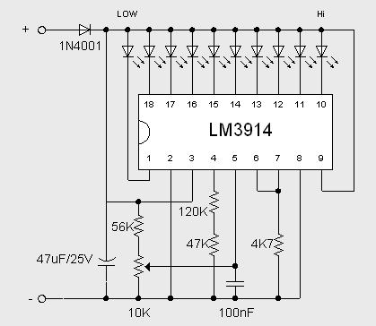
This 2 Volt Battery Monitor by IC LM3914 circuit makes it possible to monitor the charging process to a higher level. Adjustsments end are simple and all you need is a digital voltmeter for the necessary precision. Connect an input voltage of 12.65 volt between the positive and negative poles and adjust the 10K potentiometer until the LED 10 lights up. Reduce tension and the sequence of all other LED lights. Control has been an enlightening about 11.89 volts.
At 12.65 volt and higher the battery is fully charged, and 11.89 is considered "empty". This circuit, with the components shown, uses less than 10 mA. Of course you can adapt this circuit for their own needs, making small modifications. The previous circuit is set to "point" mode, which means only one LED at a time goes on. To use the mode of "bar", then connect pin 9 to the positive supply rail, but obviously with increased current consumption. The brightness of the LEDs can be adjusted up or down by choosing a different value for the 4K7 resistor connected to pin 6 / 7.
At 12.65 volt and higher the battery is fully charged, and 11.89 is considered "empty". This circuit, with the components shown, uses less than 10 mA. Of course you can adapt this circuit for their own needs, making small modifications. The previous circuit is set to "point" mode, which means only one LED at a time goes on. To use the mode of "bar", then connect pin 9 to the positive supply rail, but obviously with increased current consumption. The brightness of the LEDs can be adjusted up or down by choosing a different value for the 4K7 resistor connected to pin 6 / 7.
Subscribe to:
Posts (Atom)
