The MAX16834 is a neat little chip (its not the only one, there are plenty of others out there) that allows high efficiency designs for LED string driving. It provides a platform for a Buck or Boost converter design, as well as brightness adjustment via analog/PWM input pins, as well as a fault output (in case of open/short circuits for example) and also diverse other functionalities that can be quite useful. [Link]
Tuesday, September 23, 2014
Circuit DIY 100W LM3886 Parallel Stereo Power Amplifier
100W LM3886 Parallel Stereo Power Amplifier
Hi, meet with me again now i try to share for 100W LM3886 Parallel Stereo Power Amplifier This amplifier is based on the PA100 line amplifier elaborate in Nationalist Semiconductor's coating tell - AN1192. Since my DIY speaker is 4-ohm and somewhat challenging to swing, I poorness to tally a much effectual amplifier to deal with it. Therefore I designed this amplifier which uses two LM3886 per water, in nonconvergent track.This amp can present some 50W into a 8-ohm talker and 100W into a 4-ohm talker. This is a stereo amplifier and thence 4 LM3886s are old. The LM3886 circuit is in a non-inverted plan, so the signaling resistivity is settled by the input resistor R1, i.e. 47k. The 680 ohm and 470pF resistance capacitor strain cloth is misused to filter out the int {shot out the steep frequency noise at the LM3886 sign pins. I old upper grade frequence mark capacitors at individual locations: 1uF Auricap at the signaling for DC interference, 100uF Blackgate for C2 and C6, and 1000uF Blackgate at the render strain.for more information i fount the source for Circuit DIY 100W LM3886 Parallel Stereo Power Amplifier here
Labels:
circuit
Sunday, September 21, 2014
Simple Crystal Tester Circuit Diagram
Simple Crystal Tester Circuit Diagram. Most electronics project working with high frequency utilizes crystal in order to generate frequency as oscillator. It is used instead of coil. Coil can be checked with multi-meter if there is any fault, but checking of crystal completely is difficult. In order to solve this problem a simple project using few components is designed call crystal tester.
This circuit consist two NPN transistors, two diode with few passive component. The crystal under test is combining with transistor T1 which further work as oscillator. The combination of transistor T1, crystal under test and capacitors C1 and C2 is work as colpiitt oscillator. If the testing crystal is good then it works as oscillator with transistor T1. The output of oscillator is rectified and filtered by diode D1 and capacitor C2 respectively and given to base of transistor T2. The signal given to base conduct transistor which further glow the LED connected to the collector through resistor R3. If the testing crystal is faulty then LED1 does not glow.
Simple Crystal Tester Circuit Diagram
PARTS LIST
Resistors (all ¼-watt, ± 5% Carbon unless stated otherwise)
R1 = 27 KΩ
R2 = 1 KΩ
R3 = 560 Ω
Capacitors
C1 = 0.001 µF
C2 = 100 pF
C3 = 0.001 µF
C4 = 0.004 µF
Semiconductors
D1, D2 = 1N4148
T1, T2 = BC550C
LED1 = Green
Miscellaneous
SW1 = push to on switch
Resistors (all ¼-watt, ± 5% Carbon unless stated otherwise)
R1 = 27 KΩ
R2 = 1 KΩ
R3 = 560 Ω
Capacitors
C1 = 0.001 µF
C2 = 100 pF
C3 = 0.001 µF
C4 = 0.004 µF
Semiconductors
D1, D2 = 1N4148
T1, T2 = BC550C
LED1 = Green
Miscellaneous
SW1 = push to on switch
Simple 300w Subwoofer Power Amplifier Wiring Circuit Diagram
Subwoofer Speaker Wiring Diagram Subwoofer Review.
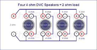
Subwoofer Wiring Diagrams Four 4 Ohm Dual Voice Coil Dvc Speakers.
300w Subwoofer Power Amplifier Wiring Diagram
Subwoofer Wiring Diagrams Two 8 Ohm Single Voice Coil Svc Speakers.
Discuss Ep4000 Maelstrom X Ii In The Diy Subwoofers Forum.
Subwoofer Wiring Diagrams Hip Hop Universe.Bazooka Subwoofer Wiring Diagram.
Need Sum Help Wiring Dual Coil Sub And Box Build Trinituner Com.
Car Subwoofer Wiring
Sub 2 Output Is An Excellent Way To Connect Your Subwoofers The Total.
Remote Field Strength Meter Circuit Diagram
Remote Field Strength Meter Circuit Diagram. This field strength meter consists of a tuned crystal detector producing a dc output voltage from a transmitted signal. The dc voltage is used to shift the frequency of a transmitter of 100-mW power operating at 1650 kHz. The frequency shift is proportional to the received field strength. This unit has a range of several hundred feet and is operated under FCC part 15 rules (100-mW max power into a 2-m-iong antenna between 510 and 1705 kHz).
Remote Field Strength Meter Circuit Diagram
Simple Hard Disk Selector Circuit Diagram
In the last few years, the available range of operating systems for PCs has increased dramatically. Various free (!) operating systems have been added to the list, such as BeOS, OpenBSD and Linux. These systems are also available in different colours and flavours (versions and distributions). Windows is also no longer simply Windows, because there are now several different versions (Windows 95, 98, ME, NT, XP, Vista and 7). Computer users thus have a large variety of options with regard to the operating system to be used. One problem is that not all hardware works equally well under the various operating systems, and with regard to software, compatibility is far from being universal. In other words, it’s difficult to make a good choice.
Hard Disk Selector Circuit Diagram
Switching from one operating system to another - that’s a risky business, isn’t it? Although this may be a bit of an exaggeration, the safest approach is still to install two different operating systems on the same PC, so you can always easily use the ‘old’ operating system if the new one fails to meet your needs (or suit your taste). A software solution is often used for such a ‘dual system’. A program called a ‘boot manager’ can be used to allow the user to choose, during the start-up process, which hard disk will be used for starting up the computer. Unfortunately, this does not always work flawlessly, and in most cases this boot manager is replaced by the standard boot loader of the operating system when a new operating system is installed.
In many cases, the only remedy is to reinstall the software. The solution presented here does not suffer from this problem. It is a hardware solution that causes the primary and secondary hard disk drives to ‘swap places’ when the computer is started up, if so desired. From the perspective of the computer (and the software running on the computer), it appears as though these two hard disks have actually changed places. This trick is made possible by a feature of the IDE specification called ‘CableSelect’. Every IDE hard disk can be configured to use either Master/Slave or CableSelect. In the latter case, a signal on the IDE cable tells the hard disk whether it is to act as the master or slave device. For this reason, in every IDE cable one lead is interrupted between the connectors for the two disk drives, or the relevant pin is omitted from the connector.
This causes a low level to be present on the CS pin of one of the drives and a high level to be present on the CS pin of the other one (at the far end of the cable). The circuit shown here is connected to the IDE bus of the motherboard via connector K1. Most of the signals are fed directly from K1 to the other connectors (K2 and K3). An IDE hard disk is connected to K2, and a second one is connected to K3. When the computer is switched on or reset, a pulse will appear on the RESET line of the IDE interface. This pulse clocks flip-flop IC1a, and depending on the state of switch S1, the Q output will go either high or low. The state on the Q output is naturally always the opposite of that on the Q output. If we assume that the switch is closed during start-up, a low level will be present on D input of IC1a, so the Q output will be low following the reset pulse.
This low level on the Q output will cause transistor T1 to conduct. The current flowing through T1 will cause LED D1 to light up and transistor T2 to conduct. The hard disk attached to connector K2 will thus see a low level on its CS pin, which will cause it to act as the master drive and thus appear to the computer as the C: drive. A high level will appear on the Q output following the reset pulse. This will prevent T3 and T4 from conducting, with the consequence that LED D2 will be extinguished and the hard disk attached to connector K3 will see a high level on its CS pin. For this disk, this indicates that it is to act as a slave drive (D: drive).
If S1 is open when the reset pulse occurs, the above situation is of course reversed, and the hard disk attached to connector K2 will act as the D: drive, while the hard disk attached to connector K3 will act as the C: drive. Flip-flop IC1a is included here to prevent the hard disks from swapping roles during use. This could have disastrous consequences for the data on the hard disks, and it would most likely cause the computer to crash. This means that you do not have to worry about affecting the operation of the computer if you change the switch setting while the computer is running. The state of the flip-flop, and thus the configuration of the hard disks, can only be changed during a reset.
The circuit is powered from a power connector for a 3.5-inch drive. This advantage of using this connector is that it easily fits onto a standard 4-way header. However, you must observe the correct polarity when attaching the connector. The red lead must be connected to pin 1. Constructing the hard disk selector is easy if the illustrated printed circuit board is used. You will need three IDE cables to connect the circuit. The best idea is to use short cables with only two connectors, with all pins connected 1:1 (no interruption in the CS line). The IDE connector on the motherboard is connected to K1 using one cable. A cable then runs from K2 to first hard disk, and another cable runs from K3 to the second hard disk. This means that it is not possible to connect more than two hard disks to this circuit. You must also ensure that the jumpers of both disk drives are configured for CableSelect. To find out how to do this, refer to the user manual(s) for the drives.
The Latest NASA Launches Instagram Account
The Latest NASA Launches Instagram Account One little step on a social newspapers platform is one giant leap for Instagram. Thats because NASA launched an authorized Instagram account on Friday — a communal profile it says will "take its followers on an out-of-this-world excursion through images of soil and beyond." According to a report issue, with content including aeronautics, astrophysics, soil science and human spaceflight, the NASA account will provide a outlook of the bureau by distributing new and historic images and videos.
On its first day on Instagram, NASA concentrated on the launch of its Lunar Atmosphere and dirt Environment Explorer, or LADEE, at 11:27 p.m. from NASAs Wallops Flight Facility on Wallops isle, Va. NASA states LADEE is a robotic research objective that will orbit the moon to gather data about the structure and composition of the lunar air and determine whether dust is being lofted into the lunar atmosphere.
By 11:30 p.m. ET on Friday, NASA was up to 32,000 followers on Instagram — including 4,000 as of that noon all through the day, NASA posted historic moon images and real-time photographs from the launch convoluted premier up to and encompassing liftoff. As of Saturday, 6,400 Instagram users had admired the LADEE launch likeness.
"Thats the topic for the day - Instagram moon day," states John Yembrick, NASAs communal media supervisor, supplementing the search to the moon would be visible from the Carolinas to Maine. According to Yembrick, NASAs Ames Research Center and Goddard Space air travel Center have living Instagram accounts, which NASA was "testing to glimpse how it went." Instagram is a good platform for the bureau because "NASA is such a visual organization," Yembrick states.
NASA has countless images to share, including those from the Hubble telescope as well as the sun.
"What we launch today with images from the moon is such a dynamic article to tell visually," he adds.
The agency furthermore utilises Flicker, Twitter, Facebook and Google+ to share photos. "NASA is trying to motivate the world to investigation and discovery. Wed actually like to come to out to let people know what were doing in space investigation and how it impacts their lives and forms the world," Yembrick states. "Id also state wed like to hit persons who use the [Instagram] stage. One of the things about [Instagram] is that you proceed on to share an facet of your life and through it you can discover what NASA is doing. You dont necessarily expect to discover, but you can if all of a rapid its in front of you. Its not just images - its telling the NASA story."
Also on Friday, Instagram handed out a tweet to welcome NASA. By the next day, it had been re-tweeted 1,000 times and favorited 500 times. The agencys primary Twitter account, @NASA, has 4.7 million followers, which NASA states is more than any other government bureau.
NASA furthermore has a occurrence on YouTube, Foursquare and Reddit, among other stages.
"Were endeavouring to evolve," Yembrick says. "Weve been on Instagram for awhile, but I wish we were on it sooner. occasionally the government doesnt move as fast, but I think its a large stage for us as we evolve and are endeavouring to come to a different demographic and audience."
NASA was established by leader Dwight D. Eisenhower in 1958. The association states its dream is "to reach for new heights and disclose the unknown so that what we do and learn will advantage all humankind."
Dual Output DC DC Power Supply for AMOLED Displays
This is a dual-output switch mode power supply reference design based on the MAX17116. The part and reference circuit can provide both negative and positive supplies to AMOLED displays. [via]
The MAX17116 includes two current-mode 1.4MHz switch mode power-supply (SMPS) regulators for active-matrix organic light-emitting diode (AMOLED) displays. The positive supply is provided by a step-up regulator with a synchronous rectifier. The negative supply is provided by an inverting regulator with a synchronous rectifier.[Link]
Tiny Synchronous Step Up Converter Design Guide
Here is a design guide from Linear Technology describing how to design boost power supplies that can work from as little as 0.7 volts. These constant voltage power supplies that can run off until nearly every last drop of power is consumed. [Link]
Build a Precision full wave Rectifier Circuit Diagram
This Precision full wave Rectifier Circuit Diagram provides accurate full wave rectification. The output impedance is low for both input polarities, and the errors are small at all signal levels. Note that the output will not sink heavy current, except a small amount through the 10K resistors. Therefore, the load applied should be referenced to ground or a negative voltage. Reversal of all diode polarities will reverse the polarity of the output
Since the outputs of the amplifiers must slew through two diode drops when the input polarity changes, 741 type devices give 5% distortion at about 300 Hz.
Precision full wave Rectifier Circuit Diagram
Since the outputs of the amplifiers must slew through two diode drops when the input polarity changes, 741 type devices give 5% distortion at about 300 Hz.
Precision full wave Rectifier Circuit Diagram
Sourced By: http://circuitsstream.blogspot.com/2013/07/precision-full-wave-rectifier-circuit.html
Introduce Lenovo Debuts 5 Inch Vibe X Smartphone
Introduce Lenovo Debuts 5-Inch Vibe X Smartphone. Lenovo unveiled its new Vibe X, a fairly clear-cut smartphone, at IFA Berlin on Thursday.
The 5-inch apparatus arrives with a 1,080p IPS display, a quad-core, 1.5GHz processor, a 13-megapixel camera (coupled with an oddly powerful 5-megapixel one on the front), 2GB of recollection and 16GB of storage.
The specs are admirable, but they arent the best out there. although, add in the premium polycarbonate body — which is just 6.9 millimeters thick and weighs about a quarter of a pound — and Vibe X becomes a solid lightweight competitor in the crowded 5-inch Android arena.
On the programs edge, just like most of its new brethren, it sprints Android 4.2. The Vibe X will never reach European or the U.S. coastlines, weve been notified. Price and release designated day are not yet available.
TL496 3 to 9 volt converter Circuit Diagram
This is simple Simple TL496 3 to 9 volt converter Circuit Diagram. it uses the TL496 power supply controller, a coil and a electrolytic capacitor. The maximum output voltage is actually 8.6V and current is around 80mA.The input current (the current drawn from the batteries) is 405mA at the maximum output current. Without load the current consumption is 125µA and the batteries life is around 166 days.
TL496 3 to 9 volt converter Circuit Diagram
USBCELL Revolutionary NiMH Rechargeable Battery
A revolutionary NiMH rechargeable battery - the USBCELL, saves you money and battery waste and is easy to recharge from a USB port. When empty, all you have to do is to plug the USBCELL in PC port. This cool eco-friendly gadget is of AA sized battery and costs $10-20. USBCELL has also been designed in the AAA format with an instant foldout full-size USB, and with a mini-USB. AA cells can also be used with convertors to create C and D size cells.
Labels:
battery,
nimh,
rechargeable,
revolutionary,
usbcell
Simple Telephone In Use Indicator Circuit Diagram
This is a Simple Telephone In Use Indicator Circuit Diagram. With this circuit mounted in or near every phone in the house, it will allow users to know if the phone is being used and not to pick up the phone. When a phone is taken off hook, the voltage across the tip and ring terminals drops to 10 volts or less. This will cause the FET (2N4360) to turn on and also turn on the transistor (2N2222). When the transistor turns on it will allow current to flow through the LED and make it light. A blinking LED could be used to make the effect better.
Simple Telephone In Use Indicator Circuit Diagram
AVR Stick – A Simple USB Data Logging Device
The AVR Stick is a simple data logging device that instantiates itself as an HID keyboard and reports the voltages, along with a ‘timestamp,’ from two pins on an ATtiny85. The device uses open source firmware availabe from Objective Development (http://www.obdev.at/vusb/) called V-USB to implement the USB 1.1 standard. The code that runs the application was based on the EasyLogger example application from Objective development. [Link]
Build a 12V 7 2Ah SMF Battery Charger Circuit Diagram
Build a 12V 7.2Ah SMF Battery Charger Circuit Diagram. The LM317 is an adjustable three-terminal positive-voltage regulator capable of supplying more than 1.5A over an output-voltage range of 1.25 V to 37 V. It is exceptionally easy to use and requires only two external resistors, R2’ and R2” (R2= R2’+ R2”) to set the output voltage. Furthermore, both line and load regulation is better than standard fixed regulators. In addition to having higher performance than fixed regulators, this device includes on-chip current limiting thermal overload protection, and safe-operating-area protection. All overload protection remains fully functional, even if the ADJUST terminal is disconnected. By connecting a fixed resistor, R1 the ADJUST and OUTPUT terminals, the LM317 can function as a precision current regulator. An optional output capacitor can be added to improve transient response.
Schematic Diagram using LM317
The ADJUST terminal can be bypassed to achieve very high ripple-rejection ratios, which are difficult to achieve with standard three-terminal regulators. A capacitor of small value should be connected across the input pin of LM317 and ground, particularly if the regulator is not in close proximity to the power-supply filter capacitor.
Please note that the output can go no lower than 1.25 Volts.The Input voltage must be about 3 Volts above the desired Output Voltage. So input voltage should be around 18V.So a transformer with the secondary voltage of 17 V is used.
Determining the Values
Vo is calculated by following formula , Vo = Vref * ( 1 + R2/R1 )
Where Vo is the voltage drop across the output i.e voltage applied to the charge the battery.
Here Vref = 1.25.Making R1 a standard value, like 220 Ohms sets the current through R2 as well. Now all we have to do is select the value of R2 to give us a voltage drop of our desired V OUT, minus the 1.25 Volts across R1.
So for Vomaximum=15 v and Vominimum=12 v we get respective values of R2minimum=1K8 and R2maximum=2K3 which we will get by keeping R2’=1k8 and R2”=500 Ohms (variable).
The most commonly used OPAMPS are 741 and 324. IC741 is used in close loop configuration and LM324 in open loop configuration. i.e. LM324 mainly used as comparator while 741 for amplification,addition etc
LM317 regulates the Output at 1.25 Volts above the Reference pin. Knowing this the value of this resistor sets the current through both resistors. The current drawn by the Reference pin is small and can be ignored as long as the current through the resistors is around 1 mA to 10 mA.
Testing your Circuit
Output voltage can be varied and obtained as wanted(between 12v and 15v,minimum and maximum charging voltages. Observed voltage values at INPUT ,OUTPUT and ADJUST pins is shown in table.While testing take enough precaution as not to short OUTPUT and ADJUST pins as it may damage the transistor BC 547,whose collector is connected to adjustment pin.
ADJUST | OUTPUT | INPUT | Vref |
13.7 V | 12.47 V | 15.01 V | 1.23 |
The difference between voltage at output pin and adjustment pin is 1.23 (~1.25) which is the reference voltage Vref. Current rating of battery to be charged 7.2 Ah 12v, short circuit current Isc = 720mA .Using multi-meter check the short circuit current.If the Isc shows a different value than expected,it can be changed by increasing or decreasing the load connected between the emitter of the transistor T1 and ground.
Working of Charger Circuit
The circuit uses two LEDs as indicators; one for signaling charging ON condition,and the other as an indicator , when charging voltage falls below its terminal voltage (~12 volts). Terminal voltage can be adjusted by adjusting the 1k Trimpot. The output voltage range can be adjusted by 500 ohm Trimpot. LM324 is used in comparator circuit,after the rectifier circuit. Comparator will compare the voltage levels,and if the output voltage is less than the charging voltage,the voltage across the red LED will go high thus indicating drop in charging voltage.
Diode Protection for LM317T
If the battery is connected to the charger but unplugged from the power source, you end up with the input voltage of the circuit disconnected while the output voltage is still present. Some regulators can be damaged by this, and thus diodes are put into the circuit to protect them.
Applications
SMF batteries or VRLA batteries (valve-regulated lead-acid battery) are made in an eco-friendly, ISO Certified & modern plant with a large manufacturing capacity and are being sold worldwide. There is a wide range available to suit all applications of standby power requirement’s, for example:
- UPS (Uninterrupted power supply)
- Inverter and Emergency Lights
- Telecommunication equipment
- Fire Alarm & Security Systems
- Railway Signaling
- Electronic Attendance & Cash Registers
- Solar Lanterns and Systems,
etc. come in factory charged conditions and have a high shelf life thereby requiring longer time intervals between recharging of batteries in stock. Source : Link
1KHz Sinewave Generator Circuit Diagram
Simple circuitry, low distortion, battery operated Variable, low impedance output up to 1V RMS
Circuit diagram
Parts:
- R1 5K6 1/4W Resistor
- R2 1K8 1/4W Resistor
- R3,R4 15K 1/4W Resistors
- R5 500R 1/2W Trimmer Cermet
- R6 330R 1/4W Resistor
- R7 470R Linear Potentiometer
- C1,C2 10nF 63V Polyester Capacitors
- C3 100µF 25V Electrolytic Capacitor
- C4 470nF 63V Polyester Capacitor
- Q1,Q2 BC238 25V 100mA NPN Transistors
- LP1 12V 40mA Lamp (See Notes)
- J1 Phono chassis Socket
- SW1 SPST Slider Switch
- B1 9V PP3
- Clip for 9V PP3 Battery
Circuit description:
This circuit generates a good 1KHz sinewave using the inverted Wien bridge configuration (C1-R3 & C2-R4). Features a variable output, low distortion and low output impedance in order to obtain good overload capability. A small filament lamp ensures a stable long term output amplitude waveform. Useful to test the Audio Millivoltmeter, Audio Power Meter and other audio circuits published in this site.
Notes:
- The lamp must be a low current type (12V 40-50mA or 6V 50mA) in order to obtain good long term stability and low distortion.
- Distortion @ 1V RMS output is 0.15% with a 12V 40mA lamp, raising to 0.5% with a 12V 100mA one.
- Using a lamp differing from specifications may require a change in R6 value to 220 or 150 Ohms to ensure proper circuits oscillation.
- Set R5 to read 1V RMS on an Audio Millivoltmeter connected to the output with R7 fully clockwise, or to view a sinewave of 2.828V Peak-to-Peak on the oscilloscope.
- With C1,C2 = 100nF the frequency generated is 100Hz and with C1,C2 = 1nF frequency is 10KHz but R5 is needing adjustment.
- High gain transistors preferred for better performance.
Build a Power On Reset Circuit Diagram
This is a simple power on switching circuit. This type of reset pulse is ideally provided by this circuit. Because of the high input impedance of the Schmidt trigger, long reset pulse times may be achieved without the excess dissipation that results when both output devices are on simultaneously, as in an ordinary gate device (B). A reset pulse is often required at power-on in a digital system. See circuit diagram below.
Simple Power On Reset Circuit Diagram
Audio Milli Volt Meter Circuit Diagram
Build a simple audio Milli volt meter circuit diagram. This Audio Milli Volt Meter Circuit has a flat response from 8Hz to 50 kHz at -3 db on tbe 10-mV range. The upper limit remains the same on tbe less sensitive ranges, but the lower frequency limit covers under 1 Hz.
Simple Audio Milli Volt Meter Circuit Diagram
Sourced By : http://circuitsdiagram-lab.blogspot.com/2013/11/simple-audio-milli-volt-meter-circuit.html
Crystal Controlled Reflection Oscillator Circuit Diagram
How to build a Crystal-controlled-reflection-oscillator circuit diagram . This is a simple crystal controlled reflection oscillator circuit, this unit is easily tunable and stable, consumes little power, and costs less than other types of oscillators tlmt operate at the same frequencies. This unusual combination of features is made possible by a design concept that includes operation of the transistor well beyond the 3 dB frequency of its current-versus- frequency curve.
Crystal Controlled Reflection Oscillator Circuit Diagram
The concept takes advantage of newly available crystals that resonate at frequencies up to about 1 GHz.The emitter of transistor Q is connected with variable capacitor Cl and series-resonant crystal X. The emitter is also connected to ground through bias resistor Rl. The base is connected to the parallel combination of inductor L and capacitor C3 through DE-blocking capacitor and C4 and is forward biased with respect to the emitter by resistors R3 and R4.
Impedance Z could be the 220-0 resistor shown or any small impedance that enables the extraction of the output signal through coupling capacitor C2. If Z is a tuned circuit, it is tuned to the frequency of the crystal.
Sourced by : http://circuitsdiagram-lab.blogspot.com/2013/11/build-crystal-controlled-reflection.html
Labels:
circuit,
controlled,
crystal,
diagram,
oscillator,
reflection
Audio Milli Volt Meter Circuit Diagram
This is a simple audio Milli volt meter circuit diagram. This Audio Milli Volt Meter Circuit has a flat response from 8Hz to 50 kHz at -3 db on tbe 10-mV range. The upper limit remains the same on tbe less sensitive ranges, but the lower frequency limit covers under 1 Hz.
Simple Audio Milli Volt Meter Circuit Diagram
Subscribe to:
Posts (Atom)